English

Can FDM be used for high-performance ceramic parts, and what are the limitations?

Table of Contents
Can FDM Be Used for High-Performance Ceramic Parts, and What Are the Limitations?
Direct Answer for FDM Ceramics
How Ceramic Feedstock Is Extruded
Debinding and Sintering Limitations
Where FDM Is a Reasonable Choice
Material-Specific Boundaries
Two FDM Buyer Scenarios
FDM Verification and RFQ Information
FDM Route Decision

Can FDM Be Used for High-Performance Ceramic Parts, and What Are the Limitations?

Direct Answer for FDM Ceramics

FDM, more generally called material extrusion, can be used to form ceramic-loaded green parts, but it is not normally a direct way to print a final dense technical ceramic. The filament or pellet contains ceramic powder and a temporary binder. After printing, the part needs debinding and sintering, and the final properties depend on feedstock, bead bonding, shrinkage, furnace control, and defects. Material Extrusion is therefore most useful when rapid development, accessible tooling, or a larger simple geometry justifies those limits. A high-performance part requires evidence for the fired state, not only a good-looking FDM print.

How Ceramic Feedstock Is Extruded

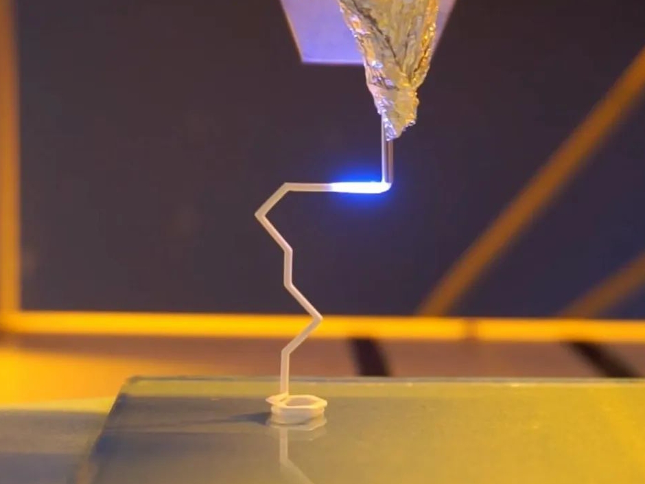
The nozzle places a ceramic-loaded road along a programmed path. Bead width, temperature, flow rate, layer height, raster angle, speed, and cooling determine how well neighboring roads bond and how uniformly the powder is packed. A feedstock with high powder loading may reduce fired shrinkage, but it can increase extrusion pressure and make flow inconsistent. A lower loading may print smoothly yet create more binder removal and larger contraction.

This is a 3D printing and additive manufacturing comparison, not a claim that FDM replaces traditional machining or molded ceramic processing in every application. Machining may still be needed after firing for a datum, bore, or sealing face, while a molded route may be more consistent for a repeated simple geometry. The useful comparison is the complete printed, debound, fired, finished, and inspected part.

Unlike a monolithic molded ceramic, the green body has interfaces between roads and layers. Those interfaces can become directional pores after firing. A tensile or flexural result in one orientation does not prove the same result in another orientation. If a load path crosses layers, the drawing and test plan should identify that orientation. The part should be evaluated as an anisotropic printed material until representative evidence shows otherwise.

Debinding and Sintering Limitations

Debinding removes the temporary binder through a controlled thermal or chemical sequence. Gas generation must remain compatible with the permeability of the part. Thick sections, sharp transitions, closed cavities, and under-filled regions can retain gas or create internal pressure, causing cracks, blisters, delamination, or distortion. A recipe used for a thin witness coupon cannot automatically be transferred to a thick housing.

Sintering then densifies the ceramic and contracts the body. Shrinkage depends on powder chemistry, loading, packing, road direction, layer direction, section thickness, setter contact, peak temperature, hold time, and atmosphere. A uniform scale factor may not correct a long rib and a short hole equally. Calibrate green-to-fired dimensions using the intended feedstock, orientation, furnace load, and representative geometry. Inspect the fired state before machining or assembly.

Where FDM Is a Reasonable Choice

FDM can be a reasonable choice for prototype housings, fixtures, casting patterns or cores, low-stress forms, and early design studies where the buyer can accept a development cycle. It may also be useful for a large, simple ceramic body that would be expensive to form with a fine optical process. The decision should account for print time, feedstock cost, debinding capacity, furnace occupancy, expected scrap, and the amount of fired machining required.

FDM is a weak first choice for a pressure boundary, a fatigue-critical thin wall, a high-impact component, or a part with very tight fired tolerances unless a qualified route already exists. The problem is not simply surface roughness. A hidden inter-road pore or debinding crack can control strength, and machining can expose or initiate a flaw. The acceptance plan needs density, dimensional, surface, and strength evidence for the actual orientation.

Material-Specific Boundaries

Alumina-filled feedstock may be selected for insulation or wear, zirconia-filled feedstock for tougher geometries, and silica-filled feedstock for casting or thermal forms. These are not interchangeable. Powder shape, loading, binder chemistry, sintering aid, and furnace atmosphere determine the final phase and density. A filament labeled ceramic may remain a polymer composite until fully debound and fired. See the ceramic 3D printing scope.

Medical, dental, electrical, and high-temperature claims require their own evidence. Printing zirconia does not establish biocompatibility. Printing alumina does not establish dielectric strength. Printing a silicon carbide feedstock does not establish a particular thermal conductivity. State the grade, final phase, density, open porosity, surface condition, service temperature, and test method. If the supplier cannot identify those conditions, keep the part in development.

Two FDM Buyer Scenarios

Large casting core. When a buyer needs a large ceramic core with complex but non-load-bearing geometry, choose FDM if the feedstock and debinding route can control gas release and shrinkage. Verify fired dimensions, collapsibility or removal behavior, surface transfer, residue, and crack condition. A core that prints quickly but distorts in the furnace can damage the casting, so the furnace trial is part of the quote rather than an optional afterthought.

Thin alumina fixture. When a fixture must insulate and fit a mating assembly, compare FDM with a finer ceramic route. Choose FDM only if the layer direction, wall thickness, fired flatness, and machining allowance are acceptable. Verify density or apparent porosity, dielectric performance, dimensions, and surface cracks after firing. If the fixture sees cyclic clamp load, add an orientation-specific strength or durability test before approval.

FDM Verification and RFQ Information

Provide CAD revision, quantity, feedstock grade, powder loading, nozzle, minimum wall, road/layer orientation, enclosed features, green/fired dimensions, shrinkage target, and debinding. State furnace schedule, machining allowance, surface, temperature, load, fluid exposure, and final state. Request feedstock lot, print/debinding records, furnace chart, fired dimensions, density/porosity, justified microscopy/CT, and a representative strength/application test.

ASTM C20 may cover applicable density/porosity and C1161 flexural testing. Use it for the actual material, orientation, surface, and fired state. Set the acceptance criterion in the drawing or quality plan; if missing, record project-specific verification and disposition, not a generic property.

FDM Route Decision

FDM suits ceramic development and simple forms, but performance depends on bead interfaces, binder removal, shrinkage, furnace distortion, and defects. Choose it when these controls are practical. Use a qualified route when anisotropy, porosity, cracks, or fired variation is unacceptable.